Top Point Fixed Glazing Plans: An Engineering & Architectural Guide
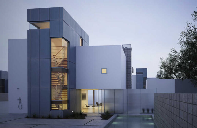
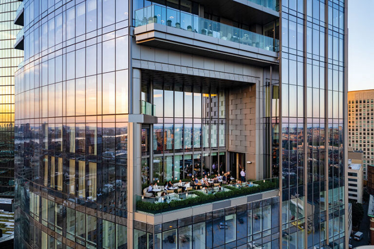
The pursuit of total transparency in modern architecture has reached its technical zenith with point-supported glazing. Unlike traditional curtain wall systems that rely on continuous perimeter framing to secure glass panes, point-supported systems—often referred to as “bolt-fixed” or “spider” glazing—utilize discrete, engineered attachments to transfer loads back to a backup structure. Top Point Fixed Glazing Plans. This approach prioritizes the visual purity of the glass, effectively turning the building envelope into a suspended, crystalline membrane. However, the apparent simplicity of these structures belies an immense level of mechanical complexity and precision engineering required to ensure long-term stability.
Implementing a successful glass facade of this nature demands a rigorous departure from standard glazing protocols. The fundamental challenge lies in the concentration of stress. In a framed system, wind loads and dead loads are distributed along the entire edge of the glass. In a point-fixed assembly, those same forces are funneled through small drilled holes or clamped points. This shift necessitates a profound understanding of glass rheology, stainless steel metallurgy, and the dynamic behavior of the building’s primary skeleton. The margin for error is measured in millimeters, and the cost of oversight is often catastrophic material failure.
For architects, engineers, and developers, the strategic development of these envelopes involves more than just selecting high-performance components. It requires a holistic view of the “load path”—the journey of force from a gust of wind on the glass surface, through the articulated bolts, into the spider fittings, and finally into the tension cables or steel trusses that hold the assembly aloft. This analysis examines the technical frameworks and strategic considerations necessary for executing the most sophisticated configurations in the industry.
Understanding “top point fixed glazing plans”
To properly define top point fixed glazing plans, one must move beyond the aesthetic desire for “clearness” and address the mechanical reality of point-supported glass. In professional engineering and editorial circles, a “top plan” refers to a specification that reconciles architectural transparency with structural safety and thermal performance. A common misunderstanding among stakeholders is that the glass is “holding itself up.” In reality, point-fixed glass is a suspended weight, and the “plan” must account for the infinitesimal movements of the building’s primary frame—sway, seismic drift, and thermal expansion—without transferring those stresses into the rigid glass.
Oversimplification is the primary enemy of these installations. Many project managers assume that point-fixed systems are modular and can be “purchased off the shelf.” This is rarely the case for high-performance facades. A robust plan must include a site-specific Finite Element Analysis (FEA) to determine how the glass will deflect around the bolt holes. If the bolts are too rigid, the glass will shatter during a high-wind event; if they are too loose, the system will leak or “rattle.” Thus, the top tier of planning involves the selection of articulated or “swivel” bolts that allow the glass to rotate slightly under load.
Furthermore, a multi-perspective analysis of these systems reveals a tension between aesthetics and physics. To an architect, the goal is a minimal spider fitting with the smallest possible footprint. To a structural engineer, the goal is a robust connection that provides enough “bite” to ensure the glass doesn’t pull through the hardware during a suction-load (negative wind pressure). The “top plan” is the document that balances these conflicting requirements through custom-engineered gaskets and specialized interlayers.
The Contextual Evolution of Point-Supported Systems
The history of point-fixed glazing is a narrative of material science catching up to architectural ambition. The precursors were the heavy, iron-framed glass houses of the Victorian era, where glass was essentially a decorative infill. The shift toward modern point-fixing began in the mid-20th century, notably with the work of Peter Rice and the development of the “Planar” system. This marked the first time glass was treated as a structural component rather than just a curtain.
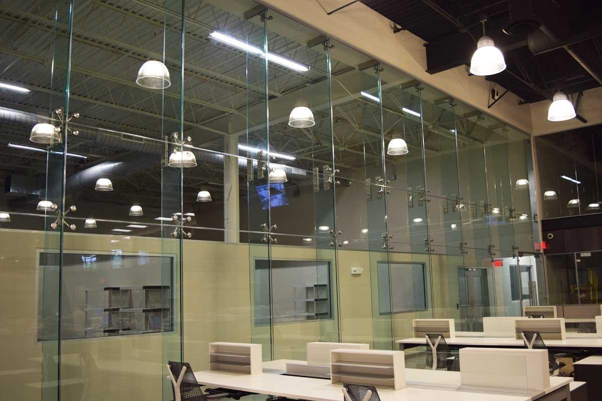
Historically, the limitation was the drilling process. Drilling a hole in glass introduces microscopic flaws that act as stress concentrators. The evolution of CNC water-jet cutting and advanced tempering furnaces allowed for the production of holes with polished interiors, which significantly reduced the risk of spontaneous fracture. Today, we have moved into the “Clamped” era, where many of the most advanced plans avoid drilling entirely, using friction-based clamps that grip the edges or corners of the glass, further distributing the load and improving the thermal performance of the unit.
Conceptual Frameworks for Stress and Load Management
1. The Articulated Joint Model
This framework treats every point of connection as a pivot point rather than a fixed anchor.
-
Application: Using ball-and-socket joints in the bolt assembly to accommodate glass deflection.
-
Limit: Increased mechanical complexity can lead to higher maintenance requirements if the gaskets degrade over time.
2. The Post-Breakage Stability Framework
A critical mental model for public safety, focusing on what happens after a material failure.
-
Application: Utilizing ionoplast interlayers (SentryGlas) that remain rigid even if the glass layers are shattered.
-
Limit: Adds significant weight and thickness to the glass units, requiring stronger support steel.
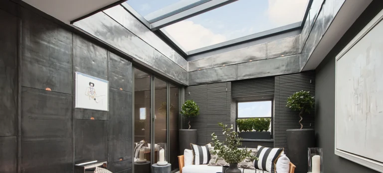
3. The Thermal Gradient Partition
Analyzing the glass not as a wall, but as a heat-transfer interface.
-
Application: Decoupling the metal spider fitting from the interior environment to prevent “cold-bridging.”
Core Categories of Attachments and Support Structures
Point-fixed systems are categorized by their “backup” structure, which provides the lateral and vertical support.
| Support Category | Mechanical Strategy | Aesthetic Impact | Trade-off |
| Glass Fin | Glass-on-glass support | Maximum transparency | Extremely high installation risk |
| Tension Cable | High-tension steel wires | Minimalist; “floating” | Sensitive to wind-induced vibration |
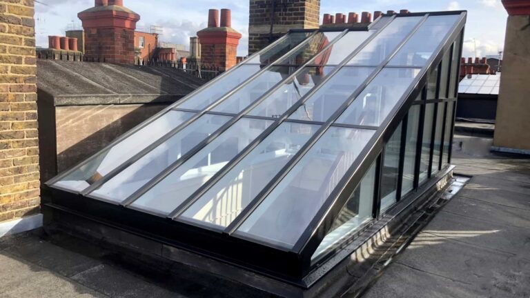
| Steel Truss | Rigid tubular/I-beam frames | Industrial; “high-tech” | Higher visual obstruction |
| Monolithic Bolt | Drilled through-bolt | High point-load | Stress concentration at holes |
| Clamped Corner | External pressure grip | Cleaner glass surface | Lower wind-load resistance |
Decision Logic for Configuration
The selection of a specific configuration is usually driven by the building’s height and exposure. For lobby podiums, glass fins are the preferred choice for their purity. However, for a high-rise facade subjected to extreme wind, a tension cable system or a rigid steel truss is often required to provide the necessary stiffness.
Detailed Real-World Scenarios and Site Constraints Top Point Fixed Glazing Plans
Scenario A: The Seismic High-Rise Lobby
In seismic zones like San Francisco or Tokyo, the point-fixed system must “dance” with the building.
-
The Conflict: The glass is rigid, but the building might move 3 inches in a lateral shift.
-
The Solution: Specialized spider fittings with “slotted” holes that allow the hardware to slide without engaging the glass.
-
Failure Mode: If the slots are too small, the hardware will “clash” with the glass edge, leading to catastrophic failure.
Scenario B: High-Humidity Tropical Atriums
In climates with high humidity and salt-air exposure, corrosion is the primary threat to the plan.
-
The Conflict: Stainless steel (Grade 304) is common but will “tea-stain” and pit in coastal environments.
-
The Solution: Specifying Grade 316 or Duplex stainless steel for all hardware and bolts.
-
Second-Order Effect: This significantly increases the material cost of the hardware package.
Economics of Transparency: Cost and Resource Dynamics
The economic profile of point-fixed glazing is heavily weighted toward soft costs—engineering, testing, and logistics—rather than just material square footage.
| Resource Item | Direct Cost Impact | Variability Factor |
| Engineered Hardware | High | Custom vs. Standard spiders |
| High-Performance Interlayers | Medium-High | SentryGlas vs. Standard PVB |
| Digital Site Survey (Lidar) | Medium | Complexity of backup steel |
| Visual Mockups (VMU) | High | Required for owner approval |
| Site Logistics (Cranes) | High | Building height and urban density |
Tools, Strategies, and Support Systems for Installation
Executing top point fixed glazing plans requires a toolkit that exceeds standard construction practices.
-
Lidar/3D Laser Scanning: Essential for mapping the “as-built” steel structure before the glass is manufactured. Glass holes cannot be redrilled on-site.
-
Vacuum Lifting Rigs: Specialized suction equipment with “articulated arms” to reach around support steel.
-
Torque-Limited Wrenches: Every bolt must be tightened to a specific Newton-meter (Nm) rating to ensure the gaskets are compressed but the glass isn’t crushed.
-
Non-Contact Gaskets: Specialized nylon or EPDM bushings that ensure no metal-to-glass contact occurs.
The Risk Landscape and Taxonomy of Failure
The primary risk in point-fixed glazing is the “compounding failure.” A small error in the steel sub-structure (e.g., a weld that is 5mm out of place) forces the glazier to adjust the bolt. This adjustment creates an uneven load on the pane, which eventually causes a “spontaneous” fracture under thermal stress.
-
Nickel Sulfide (NiS) Inclusions: A latent defect in tempered glass that causes it to explode.
-
Chemical Incompatibility: Using the wrong silicone sealant that attacks the laminated interlayer at the hole edge.
-
Dynamic Oscillation: High-frequency vibration in tension cables that “fatigues” the stainless steel spider over a 20-year period.
Governance, Maintenance, and Long-Term Adaptation
A point-fixed facade is a dynamic machine that requires a maintenance protocol.
-
Annual Visual Audits: Inspecting every bolt for “weeping” gaskets or signs of stainless steel corrosion.
-
Torque Verification: On a 5-year cycle, a sample of bolts should be checked to ensure they haven’t loosened due to building vibration.
-
Gasket Replacement: Most EPDM gaskets have a 25-30 year lifespan; the “top plan” should include a strategy for replacing these without dismantling the entire wall.
Measurement, Tracking, and Evaluation Metrics
-
Deflection-to-Span Ratio: Measuring the center-of-glass movement during high-wind events to ensure it stays within the L/175 or L/100 limit.
-
Thermal Performance Logs: Using infrared thermography to identify air leaks around the spider fittings.
-
Leading Indicators: Identifying “micro-cracks” around bolt holes using specialized polarization filters before they become structural failures.
Industry Misconceptions and Corrective Realities
-
Myth: “Tempered glass is indestructible.”
-
Reality: It is incredibly strong on the surface but fragile on the edges and at the holes.
-
-
Myth: “Stainless steel doesn’t rust.”
-
Reality: Poorly maintained Grade 304 will pit and corrode, especially in urban environments with high pollution.
-
-
Myth: “Point-fixed glass is always more expensive.”
-
Reality: While the hardware is expensive, the reduction in heavy aluminum frames and the speed of installation on certain structures can offset the cost.
-
Conclusion
The evolution of point-fixed glazing reflects a broader architectural shift toward technical maturity. It is a field where the “invisible” work—the structural modeling, the material science of interlayers, and the precision of the as-built survey—determines the success of the visible architecture. A successful installation is one where the glass appears to float, yet every millimeter of the assembly is governed by the laws of physics and the rigor of a well-executed plan. As we move toward more adaptive and resilient envelopes, the point-fixed system remains the definitive benchmark for transparency and engineering daring.